|
Setting
the Stage for Construction & Detailing
When I
opened the model kit box - I had no clue to
as how I wanted to finish it, other than
wanting to model an accurate Operation Cobra
era M4A1(76)W Medium Tank. I read through
George Winter's book a couple of times and
dug up as much information as I could on
that Sherman tank variant. I asked for some
information/advice from noted Sherman tank
researcher Kurt Laughlin to fill in some
unanswered holes too.
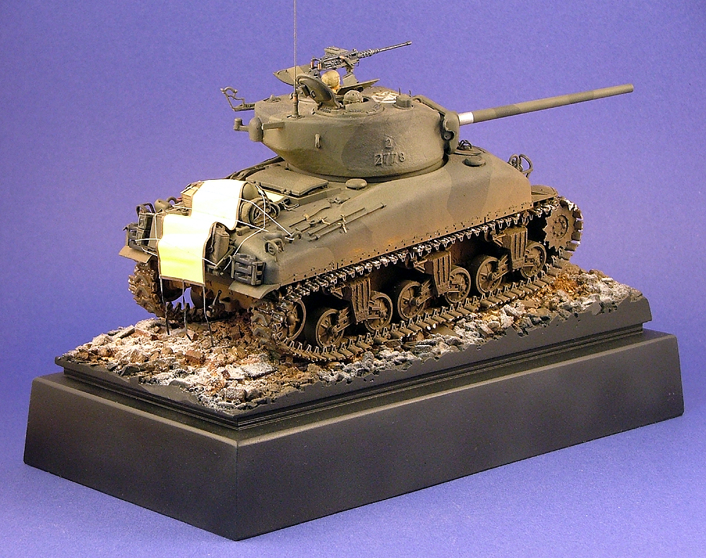
My
recipe for modeling Graham's "D-32"
M4A1(76)W was based on all the information I
gleaned from above:
Registration
Number: None, as these appear to have been
painted out/over in photos of this unit's
tanks at that time.
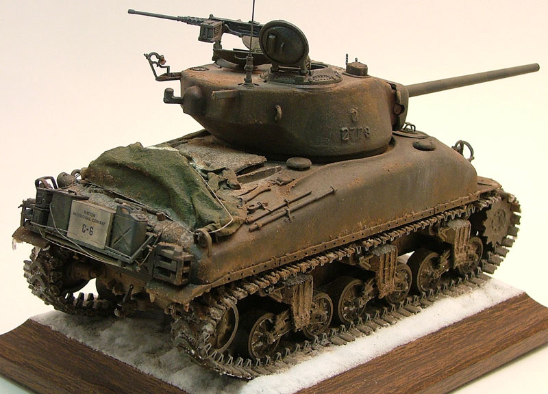
Camouflage
Pattern: Black over Olive Drab. I did not
put the chrome yellow Invasion Codes on the
turret sides, as they were generally
painted-out by this time of the war. I also
didn't "fresh-patch" the paint over where
they might have been placed either. This was
a coin toss decision, on one hand the
"fresh-patch" of paint is quite reasonable
and a common occurrence. On the other hand,
I thought that by December 24th, the crew
might have touched up the turret a little
finer than that, and went with this option.
National
Symbols: I went with US National Symbols on
the engine deck and turret roof, unbroken
rings.
Organizational
Codes: I placed these in their common
locations on the Hull, though they are
obscured by accumulated mud/dirt in the end
finish - the same as the photographed tanks
appear in the book.
Gun
Barrel: I surmised that "D-32" was one of
the initial batch of 102 M4A1(76)W delivered
to the 2nd and 3rd Armored Divisions in the
ETO, I went with M1A1 76mm Gun fit without
muzzle brake or thread protector.
Turret
and Hull: In keeping with the above thought,
consulting with Kurt Laughlin about these
vehicles, I chose to model a vehicle coming
from Pressed Steel Car Company - as they
produced this batch of Shermans delivered to
the ETO.
Pressed
Steel Car Company was an assembler of
components, not appearing to have their own
foundry for large casting of Sherman parts.
Continental Foundry produced the cast hull,
with no currently known external casting or
foundry markings. The Dragon Models kit
doesn't have any either - making this a
fortuitous choice.
Though
the Dragon Models kit turret has casting
markings present on their part, accurate for
an example on display in Bastogne, it is not
accurate for the turret casting used by
Pressed Steel Car Company. They were
provided turrets by Union Steel Company -
with uncharacteristically large casting
numbers on the turret flanks, and more
traditional ordnance numbers on the turret
roof ahead of the crew hatches. Kurt
provided me with photos of these numbers,
and I need them to get the courage to put
them on my kit part - they are so unusual I
felt no one but Kurt or Rob Ervin of
Formations Models would even know what they
represented if I took the model to a show.
Tracks:
I selected the T-48 Rubber Chevron Tracks
seen to be worn by the unit's tanks in
photos, but didn't chose the shorter
extended end connectors seen on other tanks.
Since "D-32" isn't capture in photos, I
surmised it could have worn the longer ones
I eventually went with.
Running
Gear: Solid Drive Sprocket Plates and
Solid-Spoke Road Wheels/Idler Wheels, would
be my choice - though it could have been a
combination of types. Since Dragon Models
did not include an option for backside
inserts on their Solid-Spoke Idler Wheels in
this model kit release, I used a resin set
from Formations Models.
Construction
& Detailing
I
wanted to follow Dragon Models' recommended
assembly sequence as closely as possible
along the way for detailing and corrections.
I started out wanting to build the kit as a
review subject, goal being to use as many,
if not all, the kit-provided parts during
construction. I did stick to this goal for
the most part, but couldn't help violating
it in a few instances.
Step
One: The first pieces trimmed from the sprue
trees were parts to make up the simple-plate
Drive Sprockets. There were shallow, and
easy to remove, ejector pin marks on the
inside faces of these parts (D15). There is
no positive mating between the Sprocket
Plates and the Drum, prompting me to use
several track links to line up the Sprocket
Teeth properly while the parts set. There
were some minor gaps that needed to be
filled with putty afterwards.
On the
backsides, the Dragon Models parts are not
detailed, missing plate screws and support
ribbing that I added using scrap styrene rod
and strip.
Moving
on, I really appreciated Dragon Models
inclusion of backside inserts for the
Solid-Spoke Road Wheels in this model kit.
They fit together tightly, but do result in
a small gap to fill around the
circumference. In working on this step, I
borrowed a tip from fellow Sherman modeler
Laramie Wright and trimmed back the mounting
axles on the Suspension Arms (Parts V1 and
V2) for the Road Wheels. This allows you to
put the Road Wheels in place after
assembling the Bogie Units, and keep them
separate for painting - while being able to
deal with that annoying seam to deal with
while putting the Bogie Units together. If
you are into chunking-up the rubber on your
Road Wheels, his idea makes it easier to
accomplish and add to your Bogie Units
later.
For
all the effort put into detailing the Dragon
Models kit, there is still missing detail on
the Solid-Spoke Road Wheels - principally
288 missing rivet heads around the
circumference front and back. If Dragon
Models would have included this detail on
their parts, I think I might have raved on
half a webpage about how great that was.
Is
this detail omission noticeable in the end
product? Yes. I would have gladly traded
some of the kit-provided optional photoetch,
plastic spares or brass 76mm rounds to have
gotten this detail. I wound up devoting
about three and a half hours adding these
rivet heads to my Road Wheels using Grandt
Line #153 items.
Step
Two: The Bogie Units come together in this
assembly sequence, with Dragon Models' parts
decently rendered in scale and some nifty
casting numbers in place. I would have
really liked to see the Suspension Arms and
Levers cast independently in this kit
release, though. The kit parts as presented
allow for some articulation, a "rocker"
motion, but not truly faithful to the actual
Road Wheel travel in the real Sherman.
Coupled with Dragon Models' individual track
links, the modeler could convincingly model
their kit over uneven terrain easier.
To be
fair, I did take advantage of the "rocker"
motion offered in the Dragon Models kit when
it came to assembling the individual track
link runs. I was able to set the track runs
in place on the model to dry overnight, and
remove them for separate painting and
weathering, by just being able to move the
#1 Road Wheel up and out of the way while
working with them.
I
assembled the Bogie Units, trimmed back the
axles for the Road Wheels and then putting
the resulting seams before drilling and
adding missing bolt details. I'm often left
wondering if a manufacturer will ever
present modelers with a Bogie Unit that is
cast with the entire front as a single-piece
and a simple backside insert, to eliminate
that annoying seam to remove in present kit
parts.
Bogie
Units used on the M4 series of Medium Tanks
are symmetrical, with Skids and Return
Roller Supports capable of being mounted on
either end - to make the suspension assembly
usable on either side of the tank. Sherman
modelers commonly have to drill out the bolt
holes opposite the Return Roller Mounts
whenever they put a Sherman kit together.
Nothing different in this kit release. I
also drilled out the corresponding holes on
top of the housing, opposite the front of
the Skids. I added two Grandt Line bolt
heads to represent the anchors for the
Vertical Springs, found underneath the
Skids. This detail should be countersunk,
however, I made mine raised in haste to move
forward in construction.
I felt
no need to replace Dragon Models Skids
(Parts V6), though there are thinner
aftermarket replacement available. I just
thinned the outer edges with the back of an
#11 X-Acto Knife Blade to reduce the visible
thickness. When done, I added four bolt
heads to them and glued them on the housing.
I mentioned above that I added two more
bolts on the Mounting Plate (Part V5) missed
by Dragon Models, but admit I probably did
so because I got so giddy in adding all the
extra stuff. I heartily doubt anyone would
notice them in the end product. I wound up
adding 108 more bolts and rivet heads than
another, perhaps sane, modeler would -
likely for nothing other than personal
satisfaction .
But -
that is what modeling is all about after
all. Don't let past experiences with AMS
psyche you out of going nuts on your
modeling project. If you are having fun,
then go for it! As long as it is kept in
perspective, you'll be fine.
Steps
Three, Four and Five: As called out on the
Instruction Sheet, I drilled out the
locating holes in the Rear Panel (Part H6)
with a 1.5mm drill bit. In my kit, the fit
between the Rear Panel and the lower Hull
Pan (Part Z) called for some filler putty
above and below the locations for Parts D26
& D27, and some to clean up the bottom
joint. Heck, simply thankful to have sponson
floors included in my kit from Dragon
Models, I didn't blink twice when it came to
a little trimming and seam puttying. When it
came to attaching Parts H8 and H9 to the
sponson floors, I must have misunderstood
the Instruction Sheet., and put the large
locating tabs on the outside of the Hull.
This called for later cutting away and
puttying to eliminate the joint.
Though
I commended Dragon Models for their
inclusion of backside inserts for the
Solid-Spoke Road Wheels in this kit, I was
mystified as to why there were no
corresponding inserts for the open backs of
their Solid Spoke Idler Wheels. I used a
replacement set from Formations Models. The
only detail I added to them was a set of
.005-inch styrene rings to the front and
backs of both Idler Wheels, the detail
easily seen on the real examples, but I've
never seen included on kit parts before.
Probably would be a bear to attempt to cast.
Anyway, after going overboard with bolts and
rivet heads, four rings seemed to be an
understatement.
I
experienced difficulty when attempting to
attach the Idler Wheel Mounts (Parts D26
& D27) in proper position - mine wanted
to set skewed out of alignment. I wound up
cutting the locating pins away to do so. I
do not know if this is a known problem with
the kit parts in this area. Everything else
in the assembly step fell into place without
fuss.
|
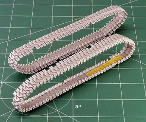
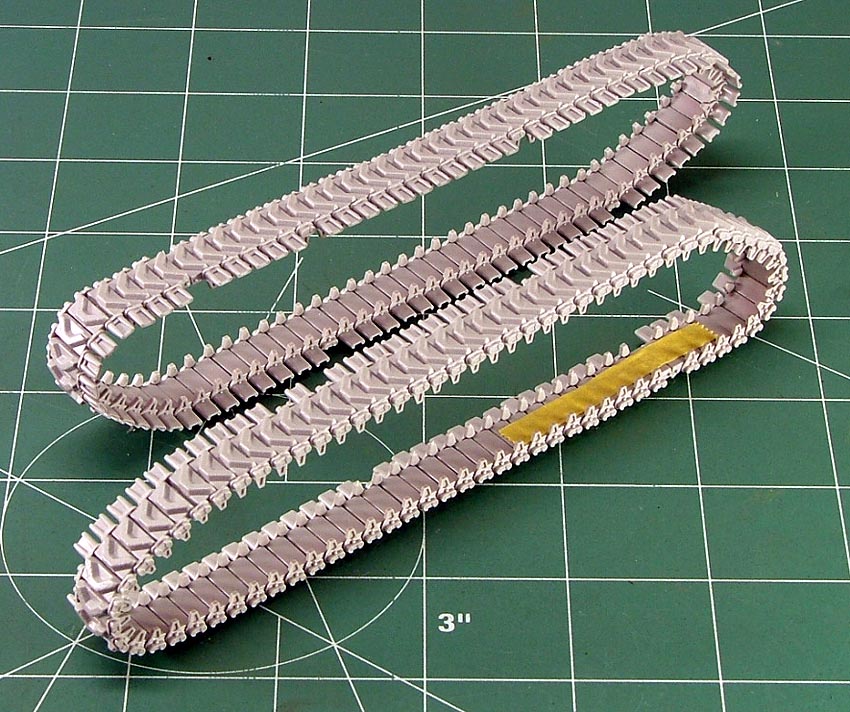
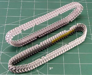
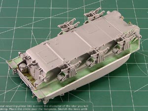
I
spent a little more than 14 hours putting
together the Dragon Models tracks included
in the kit. It took a long time and a lot of
coaxing and gently play to get them
together. I fussed all the way too,
admittedly. This was the first time I've
ever given them a go, and didn't want to
give up on them. I found that patience does
pay off, and I could actually fit them onto
my model tank's suspension to setup
overnight. In the photos shown above and
below, I left off the end connectors where
the Tamiya Masking Tape holds the ends of
the track run together. At this brake in the
track runs, I was able to slip them on and
off the model tank suspension easily, and
could paint and finish them separately until
it came time to join them permanently in the
end assembly stage. Pretty good for never
having worked with Dragon Models individual
link tracks before...
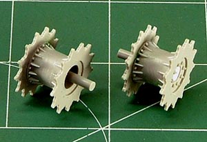
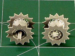
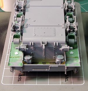
Above
and below, forgive the contrasty images, I
wanted to add some more detail to Dragon
Models' Drive Sprockets that isn't easily
seen otherwise. the stiffeners and bolt
heads are just scrap styrene stock -
time-consuming to put in place, but I wasn't
in a hurry to finish the model miniature
anyway. It adds depth of detail to match the
rest of the nice detail already present on
the model kit - and does go a bit unnoticed
in the end. I figured if someone took the
time to look, I might be served well to give
them something to look at.
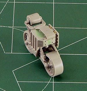
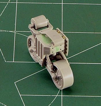
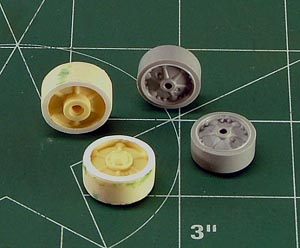
Typical
Bogie Unit with additional bolt and rivet
head details all around. Dressed up, the
Dragon Models parts look handsome. Below, a
couple of Road Wheels with rivet heads in
place front and back sides. Also, Formations
Models Idler Wheels with added Rings front
and back sides trimmed out from .005-inch
styrene stock.
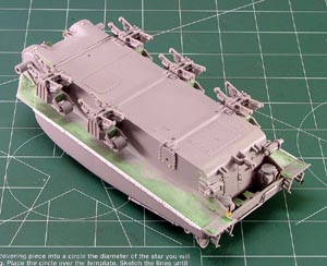
The
joint between upper and lower hulls in my
kit example called for some putty, in this
case the annoyingly-shrinkable Squadron
Green stuff. Since it is underneath the
sponson floors, and not easily seen, it
works. Above, I added a couple of missing
bolts to the mounting plates for the Bogie
Units. This detail, too, goes virtually
unnoticed in the final miniature - unless
you know what and where you are looking.
Lower photo, I added the Drainage Plates and
tried out the brass etch weld beads from
Aber for the first time. I am not sure what
I think of the final result of using them,
but underneath the sponson floors, they
don't get noticed anyway. Same goes for the
brass mesh screen at the exhausts, which
will go unnoticed once the deflector is in
place. The rest of the detail bolts on the
Bogie Units and Transmission Cover are
standard for Sherman modeling, surprising
that they still aren't there in a kit as
advanced as the Dragon Models effort.
The
Fenders included in the Dragon Model kit
were incorrect for the variant I wanted to
model. So, instead of buying an aftermarket
set, I just glued the kit parts in place,
sanded away all the detail and trimmed out
the right shapes. I thinned the underside
edges with a sharp #11 X-Acto Blade to
reduce the visible thickness and replaced
the proper details by scribing and adding
scrap styrene braces and Grandt Line rivet
heads. Traditional modeling techniques still
come in quite handy, no matter how
sophisticated the kit manufacturing process
becomes.
When it
came to attaching the Transmission
Cover, I wound up filling the joint all
around. It seems cast too short to reach
the upper Hull properly, though it was
not difficult to fill. I think in the
future I'd probably lengthen the part a
little - and figure out how to match the
cast texture rendered by Dragon Models.
Speaking of that, I appreciated the
texture cast by Dragon Models. I thought
it would look nice under thin coats of
paint, and wasn't disappointed in the end.
But, such a detail is something that one
modeler will like, and another won't. To
each his own. I added Drain Plugs to my
Transmission Cover, as well as a Comb
Device and two tie-downs. I did not add
foundry or casting numbers to my kit part,
however, because I didn't feel comfortable
with the type used by that batch of 76's
sent to the ETO. I settled on a thin coat
of accumulated dirt/mud in that area -
reasonable for 24 December, 1944.

|