|
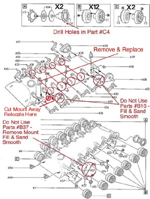
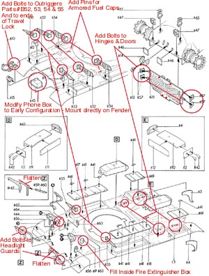
| In
an attempt to help illustrate my
recommended modifications and
additions to the basic ESCI/ERTL/AMT
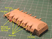
model kit Hull, I annotated my notes
on scans of the Assembly Sheet. |
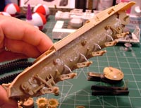
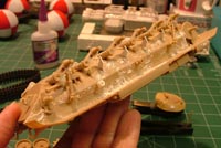
| The
ESCI/ERTL/AMT Hull is the best
1:35th scale rendition presently
available - and what I personallt
feel is the best foundation for the
M60 MBT conversion. The
modifications and corrections needed
to make it more faithful to the
actual M60 MBT are few and easy to
accomplish. The most visible of the
modifications called for come in
eliminating the second Shock
Absorber on each side, replacing the
molded-in Suspension Stops and
relocation of the forward Return
Roller - moved back towards the rear
- as all three are evenly spaced
apart. Less visible is trimming away
the hull mount for the Idler
Adjustment Arm and creating a simple
bracket to attach it to the #1
Suspension Arm. |

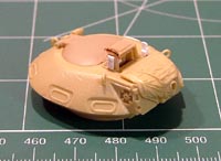

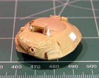
| The
AFV Club/Academy Commander's Cupola
is one of two 1:35th scale
subassemblies that I know of
presently available. The other is an
item produced by Tank Workshop - but
I haven't seen it. The above
injection-molded plastic item has a
very nice, subtle, texture and
casting numbers present on the
Cupola roof. The white piece of
styrene sheet represents the Mount
Plate for a pedestal mounted .50cal
MG seen on the M60 MBT during the
period when there were probems with
the M85 .50cal MG in the Commander's
Cupola. I modeled this feature along
with the rear turret mount provided
by CMD and a barrel clamp liberated
from a Italeri M47 Patton that was
positioned on the turret roof. |
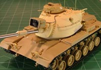
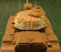
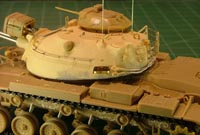
Chesapeake Model Designs'
(Early) M60 Turret and AFV Club
Commander's Cupola & Xenon Searchlight
First off, there is no such
thing as an "early" and "late" M60 Turret.
CMD points out in their instruction sheet
that they used the term to make it clearer
to the modeler that this turret is only
appropriate for the M60 MBT - and not the
later M60A1, A2 or A3 variants - in case
you're unaware of the difference.
Designed for the
ESCI/ERTL/AMT model kits, the CMD M60 Turret
is pretty complete as it comes in the box. I
used Gunze Sangyo Mr. Surfacer 500 to patch
and texture the joint between the upper and
lower halves of the Turret. The real M60
Turrets are not rough in this area, and the
Mr. Surfacer fills but does not obscure the
fine CMD cast detail.
The resin parts are thin
and cleanly cast, with little to no cleanup
issues to mention in my example. CMD's
instructions are simple, with an exploded
drawing diagram. I recommend reading them
several times until you understand how to
proceed in completing the subassembly
though.
A fine turned aluminum
barrel is included to represent the M68
105mm Gun. I admit I didn't quite understand
how to attach the accordion-like Dust Cover
to the Mantlet Cover and had to resort to
in-service photos. I sanded and set an angle
for the part that I liked in the end. CMD
instructions call for you to locate the Gun
Barrel end a scale 13 feet from the Mantlet
Cover. My 1:35th scale rulers are as welcome
as my X-Acto Knife - proving quite handy for
this purpose.
I snipped off the cast-in
handle for the Loader's Hatch and added one
made from a length of .022" solder. You
could also go as far as replacing the Hatch
Springs too - but I opted not to. I liked
the detail already present. The CMD Turret
had preset holes for the Stowage Handles on
either side, but I found that none of the
plastic parts I had fit these locations. No
problem, I fashioned my own Stowage Handles
using .022" soldier.
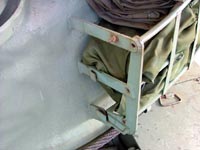 This sounds
like a difficult medium to work with, but
really isn't. When finished, the solder
parts are strong - you just have to be
careful in handling so as not to bend them
out of shape. You shouldn't paw your
precious miniatures anyway! I first inserted
lengths of solder into the holes, and set
them in place with super glue and
accelerator. I trimmed them all to the same
length. Then, I cut a length of solder and
attached it to each leg with a drop of super
glue and accelerator to hold it in position.
It took only a few minutes and looks nice in
place. This sounds
like a difficult medium to work with, but
really isn't. When finished, the solder
parts are strong - you just have to be
careful in handling so as not to bend them
out of shape. You shouldn't paw your
precious miniatures anyway! I first inserted
lengths of solder into the holes, and set
them in place with super glue and
accelerator. I trimmed them all to the same
length. Then, I cut a length of solder and
attached it to each leg with a drop of super
glue and accelerator to hold it in position.
It took only a few minutes and looks nice in
place.
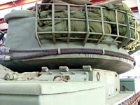
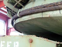 The Turret
Bustle is also done with .022" solder - as
is the rod welded along the rear bottom edge
seen at left and below. CMD provides you
with a neat jig to set the Bustle Rack
braces in place properly - assuring you that
they were not always symmetrical on the real
M60. Once the braces were glued into place
with super glue and accelerator, I went back
and added the lengths of solder. Working
slowly, the Bustle Rack came together
without a problem. I made the bracing strips
out of lengths of .010" foil - again using
patience, superglue and accelerator. The Turret
Bustle is also done with .022" solder - as
is the rod welded along the rear bottom edge
seen at left and below. CMD provides you
with a neat jig to set the Bustle Rack
braces in place properly - assuring you that
they were not always symmetrical on the real
M60. Once the braces were glued into place
with super glue and accelerator, I went back
and added the lengths of solder. Working
slowly, the Bustle Rack came together
without a problem. I made the bracing strips
out of lengths of .010" foil - again using
patience, superglue and accelerator.
 Both
Antennas are made from lengths of .015"
brass wire. I originally attempted to model
the antennae with .022" solder, but this
proved too flimsy for application. It was
just too nerve-wracking to have to watch out
for the solder everytime I handled the
model. Both
Antennas are made from lengths of .015"
brass wire. I originally attempted to model
the antennae with .022" solder, but this
proved too flimsy for application. It was
just too nerve-wracking to have to watch out
for the solder everytime I handled the
model.
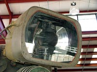 The Power
Cable for the Xenon Searchlight is a length
of .050" rosin core solder. The Xenon
Searchlight Unit I used comes from the AFV
Club M48H model kit - as I liked the detail
better. The "face" of the searchlight was
detailed with Grandt Line bolts (Note that
the photos show screws on the face), and the
inside of the unit was done with aluminum
foil super glued to .020" lead foil. The Power
Cable for the Xenon Searchlight is a length
of .050" rosin core solder. The Xenon
Searchlight Unit I used comes from the AFV
Club M48H model kit - as I liked the detail
better. The "face" of the searchlight was
detailed with Grandt Line bolts (Note that
the photos show screws on the face), and the
inside of the unit was done with aluminum
foil super glued to .020" lead foil.
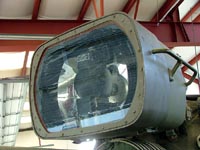 The lead
foil is easy to cut into shape and bend into
an insertable reflector housing in which you
can insert the "bulb". I had to trim out my
own "glass" face for the Searchlight, and a
mask to protect the finished interior during
painting and finishing the exterior. The
small thumbnails below are links to
additional photos of the mount itself -
rather confusing in the model kit(s).
Clicking on the thumbnail provides a larger
photo. The lead
foil is easy to cut into shape and bend into
an insertable reflector housing in which you
can insert the "bulb". I had to trim out my
own "glass" face for the Searchlight, and a
mask to protect the finished interior during
painting and finishing the exterior. The
small thumbnails below are links to
additional photos of the mount itself -
rather confusing in the model kit(s).
Clicking on the thumbnail provides a larger
photo.


 I also
liberated the Commander's Cupola from the
AFV Club (Academy) model kit because I liked
the detail better. To this, I added the
Hatch from an ESCI/ERTL/AMT M60A3 and the
Sight Housing from the M60A1 base kit I was
using. To this subassembly, I added the
mounting plate for the Pintle that mounted
on the early M60 tanks, and drilled out the
four bolt locations on the corners. This
subassembly does not fit tightly in the CMD
Turret as it was not intended to mount on
this aftermarket item, so I had to add
little locator stubs underneath to keep it
seated and aligned properly on the Turret
roof. The right edge of the Cupola locates
49 inches off the tank's centerline. I also
liberated the Commander's Cupola from the
AFV Club (Academy) model kit because I liked
the detail better. To this, I added the
Hatch from an ESCI/ERTL/AMT M60A3 and the
Sight Housing from the M60A1 base kit I was
using. To this subassembly, I added the
mounting plate for the Pintle that mounted
on the early M60 tanks, and drilled out the
four bolt locations on the corners. This
subassembly does not fit tightly in the CMD
Turret as it was not intended to mount on
this aftermarket item, so I had to add
little locator stubs underneath to keep it
seated and aligned properly on the Turret
roof. The right edge of the Cupola locates
49 inches off the tank's centerline.
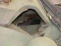
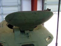 I provided
a couple of photos of the area underneath
the .50cal Mantlet for you next. It is open
on the kit parts. I hope my accompanying
photos help you if you wish to add detail in
this area. I provided
a couple of photos of the area underneath
the .50cal Mantlet for you next. It is open
on the kit parts. I hope my accompanying
photos help you if you wish to add detail in
this area.
 AFV Club
model kit Rangefinder blisters and Lift
Rings were added to the Turret - as CMD does
not provide these in their kit. I added an
Italeri .50cal MG Stowage Clip, and two
Guards from other ESCI/ERTL/AMT M60 kits
that were mounted to protect the Xenon
Searchlight when mounted for operation and
when stowed on the side of the Turret. Not
all M60 tanks show these fitted, as they
were removed by the crews. Another length of
embroidery thread mimics the chain/pin
detail on the Guard in front of the
Commander's Cupola, and for the Cap on the
.50cal MG Mount on the Turret Rear. AFV Club
model kit Rangefinder blisters and Lift
Rings were added to the Turret - as CMD does
not provide these in their kit. I added an
Italeri .50cal MG Stowage Clip, and two
Guards from other ESCI/ERTL/AMT M60 kits
that were mounted to protect the Xenon
Searchlight when mounted for operation and
when stowed on the side of the Turret. Not
all M60 tanks show these fitted, as they
were removed by the crews. Another length of
embroidery thread mimics the chain/pin
detail on the Guard in front of the
Commander's Cupola, and for the Cap on the
.50cal MG Mount on the Turret Rear. 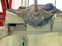
An Accurate Armour Jerry
Can Holder and Aber tie-downs were added to
their appropriate locations on the Turret -
one behind the Jerry Can and nine on the
rear right upper area at the Bustle Rack. I
used a set of Formations Models Tow Cables
to round out the Turret details.
I added more details to the
Turret Roof of my miniature appropriate to
the early M60 MBT's in accordance with the
photos here. These were provided through the
kind assistance of Joe Daneri. 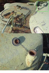 This photo
shows good detail of the mounting plate for
the .50cal MG on the side of the Commander's
Cupola, the Stowage Clip for the .50cal MG
Barrel on the Turret Roof (next to the Guard
to prevent the Cupola MG from firing into
the Xenon Searchlight when stowed) and the
Mount for the .50cal MG on the rear wall of
the Turret. The Mount for the rear Turret
wall is provided in the CMD Conversion - but
I capped it off. The Cupola Mount Plate,
Spring Clip and Guard are details you'll
have to add yourself. I described my sources
in the rest of the text on these pages. This photo
shows good detail of the mounting plate for
the .50cal MG on the side of the Commander's
Cupola, the Stowage Clip for the .50cal MG
Barrel on the Turret Roof (next to the Guard
to prevent the Cupola MG from firing into
the Xenon Searchlight when stowed) and the
Mount for the .50cal MG on the rear wall of
the Turret. The Mount for the rear Turret
wall is provided in the CMD Conversion - but
I capped it off. The Cupola Mount Plate,
Spring Clip and Guard are details you'll
have to add yourself. I described my sources
in the rest of the text on these pages.
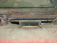 Lastly, in
measuring the real vehicle, I noted that
there is a half-inch gap between the Turret
and the Race that is visible from casual
viewing distances - and would be noticable
in 1:35th scale. The gap was wide enough to
be able to see the turret seals for fording
streams. I added small lengths of .015"
styrene strip to unseen areas beneath the
CMD Turret to elevate it. This is a very
small improvment, but one that I liked and
was easy to do. Lastly, in
measuring the real vehicle, I noted that
there is a half-inch gap between the Turret
and the Race that is visible from casual
viewing distances - and would be noticable
in 1:35th scale. The gap was wide enough to
be able to see the turret seals for fording
streams. I added small lengths of .015"
styrene strip to unseen areas beneath the
CMD Turret to elevate it. This is a very
small improvment, but one that I liked and
was easy to do.
Backdating and Improving
the ESCI/ERTL/AMT Model Kit Hull
Consulting photos of
restored M60 main battle tanks, coupled with
the Technical Manuals on the M60 Series, I
set out to make the necessary modifications
to the base ESCI/ERTL/AMT M60A1 kit parts to
model a M60 Hull.
I followed the suggested
assembly sequence and made my modifications
along the way. The ESCI/ERTL/AMT model kits
are the best renditions of the M60 series
tanks in 1:35th scale currently available -
and this made working on my conversion that
much more enjoyable. I experienced no
serious problem during assembly to warn you
about - encouraging further exploration of
the particulars of the conversion. There
were ejector pin marks, sinkholes and some
minor flash to remove from the parts in my
model kit - none too difficult to deal with.
On the positive side, the parts sport nice
texture for the cast areas of the Hull and
Turret, including casting/foundry markings
and numbers. These being noteworthy detail
additions for their time. I annotated the
Instruction Sheet at left for modifications
and changes I made to my model kit - all but
one hidden by the angle of the drawing. All
the modifications are mentioned in the text
and photos to follow however.
My kit's Upper Hull was
cleanly cast, with some minor filling called
for on the sides of the Storage Bins. I
filled them with super glue and accelerator.
There were no annoying morotization holes to
fill in the lower hull pan. The three major
pieces that make up the Hull went together
without a problem. I filled the joints and
minor gaps with Gunze Sangyo Mr. Hobby brand
Mr. White Putty.
|
Wanting to
keep my final finish and weathering light, I
applied Liquitex Acrylic Light Modeling Paste
to the undersides of the sponsons and Hull
sides. I applied the Paste with a scrap paint
brush and let it setup for a few minutes.
Then, I went back over and textured the areas
with a portion of a Sea Sponge. This works
great for subtely simulating accumulation of
dirt and mud without going overboard.
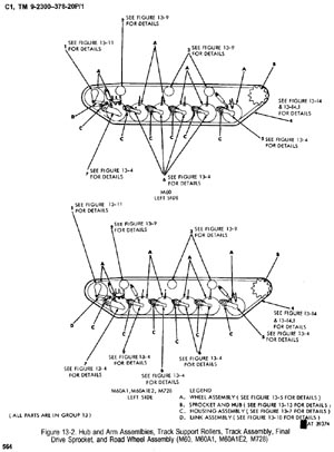 Though very
similiar to the M60A1, the Hull of the M60
differs in numbers and locations of certain
fittings. The ESCI/ERTL/AMT model kit's
bulges running along the side of the lower
Hull have notches cast into them that I
could not find on the actual M60 tank. I
filled these gaps with super glue and
accelerator. Though very
similiar to the M60A1, the Hull of the M60
differs in numbers and locations of certain
fittings. The ESCI/ERTL/AMT model kit's
bulges running along the side of the lower
Hull have notches cast into them that I
could not find on the actual M60 tank. I
filled these gaps with super glue and
accelerator.
The
M60's #2 Road Wheel does not have Shock
Absorbers - so I removed the mounting points
and restored the cast texture in this area.
I also deleted the Lift Rings (not shown
here in the above Technical Manual drawing)
from the M60A1 model kit, and filled the
locating depressions. The area underneath
the sponsons of the M60 are relatively clean
and neat and these two large lift rings are
not present on the M60 Hull.
I
fashioned replacement Suspension Arm Stops
(for lack of the proper term) and cut away
the simple castings on the ESCI/ERTL/AMT
Hull bottom - which bore little resemblance
to the items on the real M60. The backsides
of all the Suspension Arms need to be filled
as well.
Contrary
to the TM drawing above, the M60's Return
Rollers were evenly spaced apart - with the
front Return Roller only moved forward to
the position shown above in the M60A1 and
later vehicles when the second Shock
Absorber was added. I cut the mounts away
and replaced them with scrap styrene tubing
- relocating the mounts 14 scale inches to
the rear.
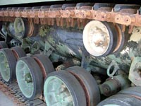 Left Above
and Below, I made the replacement Stops
using .030" styrene strip, cut to shape.
Using the Road Wheels temporarily tacked
into position, I glued the stops into place
and simulated the weld beads with acrylic
gel medium. Left Above
and Below, I made the replacement Stops
using .030" styrene strip, cut to shape.
Using the Road Wheels temporarily tacked
into position, I glued the stops into place
and simulated the weld beads with acrylic
gel medium.
 Another
view of the actual Stops on the M60 Hull,
along with Return Roller and Road Wheel
detail. Another
view of the actual Stops on the M60 Hull,
along with Return Roller and Road Wheel
detail.
The
M60 was fitted initially with side-loading
air cleaners. At left, the early and late
model side-loading air cleaner styles are
shown. I went with the early side-loader as
provided in the ESCI/ERTL/AMT model kit.
The
attachments for the Shock Absorbers to the
Suspension Arms are a bit simplified and not
100% accurate in the ESCI/ERTL/AMT model kit
- but at least they're present.
 Other M60 series kits lack
this feature. The backs of the Suspension
Arms could use additional detail in the
form of caps to close off the open ends
behind the Road Wheel axles at the least.
Part #B37 (Idler Wheel Damper) does not
locate into the Hull, as molded in the
ESCI/ERTL/AMT model kit.. Trim and fill
this locator away - and attach the Damper
to the Suspension Arm. Other M60 series kits lack
this feature. The backs of the Suspension
Arms could use additional detail in the
form of caps to close off the open ends
behind the Road Wheel axles at the least.
Part #B37 (Idler Wheel Damper) does not
locate into the Hull, as molded in the
ESCI/ERTL/AMT model kit.. Trim and fill
this locator away - and attach the Damper
to the Suspension Arm.
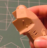 While
you're at it, filling the backs of the
Drive Housings is called for in building
the ECSI/ERTL/AMT model kit Hull. Simple
pieces of styrene sheet comes in handy for
this seemingly small detail - that's easy
to miss if you get ahead of yourself -
like I do sometimes! Instead of
freehanding it, make it easy on yourself
and cut a scrap piece of paper out and
make a pencil tracing of the opening. Trim
your new template out and use it to cut
out the shape on the sheet styrene. Test
fit and trim as necessary. While
you're at it, filling the backs of the
Drive Housings is called for in building
the ECSI/ERTL/AMT model kit Hull. Simple
pieces of styrene sheet comes in handy for
this seemingly small detail - that's easy
to miss if you get ahead of yourself -
like I do sometimes! Instead of
freehanding it, make it easy on yourself
and cut a scrap piece of paper out and
make a pencil tracing of the opening. Trim
your new template out and use it to cut
out the shape on the sheet styrene. Test
fit and trim as necessary.
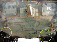 Circled
in the photo here are Drain Covers for the
Transmission and Engine - missing from all
the M60 series model kit Lower Hull pans.
The detail is easy to miss, unless you're
familar with the M60 series like Tankers
are. Adding it isn't difficult using
styrene sheet and your favorite scale Bolt
Heads. Circled
in the photo here are Drain Covers for the
Transmission and Engine - missing from all
the M60 series model kit Lower Hull pans.
The detail is easy to miss, unless you're
familar with the M60 series like Tankers
are. Adding it isn't difficult using
styrene sheet and your favorite scale Bolt
Heads.
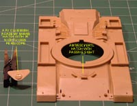
Another
modification to my miniature is a revised
Driver's Hatch. Again, thanks to Joe
Daneri, I could improve my miniature's
fidelity to the actual M60 MBT by modeling
the correct Hatch. M60 MBT Driver's
Hatches were equipped with an IR Night
Periscope. The M60A1, A2 and A3 used a
newer night vision sight - appropriately
molded in the ESCI/ERTL/AMT M60A1 model
kit as I used here for this project.
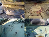 In the
photo at right, the M60 MBT Hatch is
called out by caption #2. Caption #1 shows
the M60A1 passive sight equipped Driver's
Hatch. Caption #3 shows Driver's Hatches
that were modified from IR Night Vision
Periscopes to Passive Sights, with Caption
#3 from a late model CEV made from an
M60A1 Hull and Caption #4 on an M60A3 TTS
rebuilt from an M60A1. In the
photo at right, the M60 MBT Hatch is
called out by caption #2. Caption #1 shows
the M60A1 passive sight equipped Driver's
Hatch. Caption #3 shows Driver's Hatches
that were modified from IR Night Vision
Periscopes to Passive Sights, with Caption
#3 from a late model CEV made from an
M60A1 Hull and Caption #4 on an M60A3 TTS
rebuilt from an M60A1.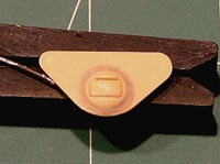
The
AFV Club/Academy Hatch can be improved
further by adding a little more contour
around the Periscope blister with some
putty to better represent the actual. I
used a small bit of Apoxie Sculpt for this
detail. I tried to present a photo with
enough contrast here to see the Apoxie
Sculpt worked around the IR Periscope
blister. The tan color of the bare plastic
plays havoc with the meter on my camera.
Anyway, the Apoxie Sculpt has a working
time from 1 to 3 hours - plenty of time
for this process. I worked a little string
rolled between my fingers into position
using a wet (water) paintbrush, and then
smoothed it out. If you'll notice, I did
not drill out the Driver's Hatch cast into
the ESCI/ERTL/AMT upper Hull. I used my
modified Hatch as a master to cast in
Alumilite instead. I holled out the
underside with my battery-powered Dremel
tool and slipped the new Hatch as a cap
over the original kit part. Why? No answer
other than I wanted to see if I could pull
the idea off. Never be afraid to try
unconventional approaches in modeling -
you'll always learn something new if you
do...
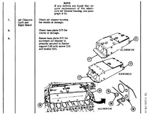
At
left, the TM illustrates the aluminum and
the armored versions of the later
top-loading air cleaners. Depending on the
time period and the unit your choose to
model your M60 tank - either style of side
or top-loading air cleaners would be
appropriate.
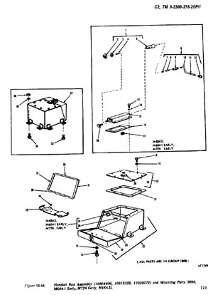
Modifying the Infantry Phone Box to the
style fitted to the M60 is easy, the
drawing at the left shows the Handset Box
Assembly as fitted to the M60, and the
difference between it and the later style
fitted to the M48A3, early M60A1 and early
M728 tanks. I sanded away the offending
detail and added my own Grandt Line #153
boltheads and a clasp from scrap solder
and foil. The Infantry Phone Box was
bolted directly to the Fender in the early
M60. Naturally, this was modified in the
field like the retrofitting of later style
Air Cleaners, and some photos of restored
vehicles show the Phone Box mounted on a
shelf. A short length of solder imitates
the cable running behind the Phone Box.
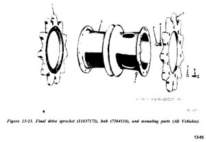
I
drilled out the mud holes in the Drive
Sprockets missing from the model kit
parts. Simple task to accomplish, I just
drilled two adjacent holes, and reamed out
the shape with a mini-file. There are
three holes each, spaced equidistant
apart. I read elsewhere on the Internet
that a modeler performing the same
conversion recommended that the Guide
Rings be eliminated on the M60 Drive
Sprockets, but I could not confirm this.
The Technical Manuals on the M60 Series of
MBT's present contradictory information
and all the photos I've seen of M60 tanks
in the fied show the Guide Rings in place.
In
my version of the ESCI/ERTL/AMT model kit,
I was missing a couple of parts for the
Drive Sprocket subassembly. I fitted
examples from AFV Club's (Academy) M48H
model kit. These fit without problem to
the ESCI/ERTL/AMT model kit.
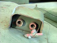
Minor
detail additions to the Hull come in
blanking off the interior of the external
Fire Extinguisher Box mounted on the
Glacis with scrap styrene strip and very
short lengths of .022" solder to mimic the
activators. .015" solder lengths were
added as pins for the Armored Fuel Caps -
which go just about hidden in the end
result behind the Air Cleaners and
underneath the Turret rear overhang.
The
Outriggers (braces that support the
Fenders) are acceptable as presented in
the ESCI/ERTL/AMT model kit, but do
benefit from minor thinning of the tops
with a sanding stick to reduce the
thickness. Photoetch replacement parts are
too thin for replicating these parts. I
added Grandt Line #135 Bolts to the
brackets that secure the Outriggers to the
Hull to replicate missing detail in the
model kit. You'll need eight bolts per
Outrigger - 64 bolts in total. Outrigger
#1 (Front Fender) calls for two bolts to
be added on each side. I used Verlinden
resin bolts for this detail.
I
replaced the kit Headlight Units with
excellent resin examples from Grief
Accessories (#GF 025). Grief's set
includes the clear and blackout lights are
separate lenses, providing a superior
result when finished. The model kit's
Headlight Guards are also missing the
mounting brackets that are welded to the
Glacis. You can easily add this little
detail to enhance the area without a great
deal of extra effort.
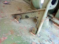
The
model kit's Personnel Heater Exhaust was
improved by drilling out the end and
adding two Clamps made from lengths of
Foil and secured with Verlinden resin
bolts. The M60 has a capped port for the
xxxxx - which I made with scrap styrene
strip sanded to shape and two Verlinden
resin bolts glued to either end.
Moving
to the rear, a small length of embroidery
thread was added to the Tow Hitch pin, I
added Verlinden bolts yet again to the
Travel Lock and incorporated Grandt Line
bolts to add missing detail on the Engine
Access Doors and Hinges too. All the
Engine Grill Hinges call for added bolt
detail. You can easily add over one
hundred bolts to the ESCI/ERTL/AMT model
kit before you realize it.
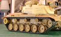
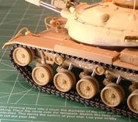
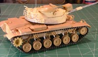
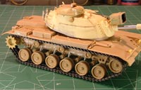
Using
Academy's Poly-Vinyl Track Runs
Academy's
M48A5K model kit provides a suitable set
of poly-vinyl tracks that I chose to fit
to my miniature. I couldn't obtain a set
of AFV Club track links in time for my
project. The Academy track runs are quite
stiff though, reminiscent of the track
runs provided in Italeri's M4 Sherman and
newer LVT series Amtrack model kits.
First
off, I joined the ends of the track runs
with the traditional heated tool to
mushroom the connecting pins. This
provided a pretty strong bond. Next, I
cleaned up the seams on the end connectors
with a steel wire brush inserted into my
battery-powered Dremel tool. Next, I setup
a pot of water on the stove, heating it to
approximately 107 degrees. Using a pair of
tongs, I dipped a track run into the hot
water for a few seconds (between five and
ten). Then, I took it out of the water,
stretched and pinched the ends until it
held the shape I wanted it to be. This
method takes out warps and radical bends
old poly-vinyl tracks set into when in a
box for a long period of time. I only had
to dip the track runs a couple of times to
straighten them out and set them into a
much better shape to fit around the
ESCI/ERTL/AMT Suspension.
Very
quickly, I attached the track runs to my
model miniature, for them to cool and
setup in "shape". The fit of my Road
Wheels, Idlers and Drive Sprockets were
loose, so I wrapped short lengths of
Tamiya Masking Tape around the locator
stubs on every suspension arm. This kept
the wheels tightly attached to the model
tank's Hull. As I used Academy's Drive
Sprockets there were no problems with the
track runs fitting tightly around the
Sprocket Teeth. In the end, I saved two
hours (lt least) over what I would have by
fitting my first choice AFV Club
individual track links. The Academy
poly-vinyl track runs became quite rigid
and setup tighty as they cooled on the
model tank Hull, and would eventually only
need a tiny drop of 5-minute epoxy to coak
them down to contact the Return Rollers.
They look good in place and you can even
see a little daylight between the links -
like you would with the individual sets.
With
the tracks in place and everything else
press-fit for photography, the M60
miniature took on an agressive stance -
this was a pretty good looking tank - just
big!
How
Close Does the Miniature Measure Up to
the Real M60 MBT?
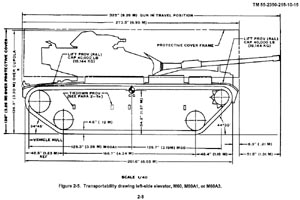 Technical
Manual 55-2350-215-10-15 provides
transportability drawings that I used to
check the overall dimensions of the
assembled model miniature - more for fun
than anything else. I had already
gleefully charged into building it and
wasn't about to go back and take it apart
again. The Technical Manual information is
useful for future projects though - who
can build just one M60 series model tank? Technical
Manual 55-2350-215-10-15 provides
transportability drawings that I used to
check the overall dimensions of the
assembled model miniature - more for fun
than anything else. I had already
gleefully charged into building it and
wasn't about to go back and take it apart
again. The Technical Manual information is
useful for future projects though - who
can build just one M60 series model tank?
 The
assembled model M60 tank looks pretty nice
from all angles and that got me curious to
investigate how close it matched the real
vehicle in overall scale. The
assembled model M60 tank looks pretty nice
from all angles and that got me curious to
investigate how close it matched the real
vehicle in overall scale.
Measured
from Fender to Fender (minus the Mud Flap)
the model falls some four scale inches
short (3mm) of the posted 273.5 inch
length. In comparing the rest of the model
Hull dimensions, the measurement from the
centerline of the Drive Sprocket to the
centerline of Road Wheel #6 falls some 3.5
inches short in scale as well. The Angle
of Departure and Angle of Approach do come
very close to the TM drawings and the
distance between the Idler Wheel and Road
Wheel #1 matches.
The
TM drawings suggest that the Hull length
is 257 inches - which the ESCI/ERTL/AMT
Hull matches in scale. To correct the
distance between the Drive Sprocket and
Road Wheel #6, and maintain the proper
spacing between the rest of the Road
Wheels and Idler and Return Rollers, would
call for more work than most would
consider warranted to gain a couple of
millimeters. The model kit's basic
assembly looks very nice and the shortage
is not very noticable in the final
product.
Vertically,
the ESCI/ERTL/AMT model comes out better.
The Hull sits above the posted Ground
Clearance of 14 inches - by a couple of
scale inches. The overall height, measured
from ground to the top of the Sight
Housing on the Commander's Cupola is 126.3
inches - which my finished miniature
matched despite using an aftermarket
Turret and Cupola from another model kit.
Ground
to top of Bustle Stowage Rack at 98.6
inches matched, Ground to top of Return
Roller/Bottom of upper track run at 54.2
inches matched, Ground to top of Fender
Stowage Bins at 69.1 inches and Ground to
top of Air Cleaner (side-loading) at 72.2
inches matched as well in miniature.
The
model miniature's width matches up with
the TM drawings, with a scale overall
width of 143 inches, Road Wheel track
(outer wheel edge to outer wheel edge) of
130 inches and Track center to Track
center of 115 inches. The Academy
poly-vinyl track runs I fitted to my
miniature are narrower than the 28 inch
track span posted in the drawing by 2
scale inches, but still slightly extend
beyond the Fenders when attached to the
model. Though they look fine once in
place, this isn't in strict fidelity to
the real tank. All in all, the measurement
exercise was fun and I didn't feel
compelled to mess around with the Road
Wheels, Drivers and Track width this time
around. The model kit captures the look
and feel of the M60 MBT quite nicely for
what I was seeking in modeling the
subject.
|